Today I learned about excess-3 encoding, from footnote 10 in the linked article. Its interesting to see how clearly the early computers were intended to work with decimal while retaining the simplicity brought by using the two signal levels of binary. Footnote reproduced here:
The computer uses excess-three encoding for digits, adding 3 to the value before converting to binary. For example, 6 is represented as binary 1001. The advantage of this encoding is that flipping the bits yields the 9's-complement decimal value, simplifying subtraction. For example, flipping the bits of 6 yields binary 0110, which is 3 in excess-3 notation. Excess-3 representation also handles carries correctly; if you add two numbers that sum to 10, the excess-3 values will sum to 16, causing a binary carry. To convert the sum to excess-3, The value 3 must be added (if a carry) or subtracted (if no carry).
To see how addition works with excess-3, 2 + 4 in excess-3 is binary 0101 + 0111 = 1100. Subtracting 3 yields 1001, which is 6 in excess-3. But 2 + 9 is binary 0101 + 1100 = 10001, generating a carry out of the 4 bit value. Adding 3 yields 0100, which is 1 in excess-3. Considering the carry-out, this is the desired result of 11.
Some early computers, as early as the 01940s, used binary; others used decimal, typically BCD but sometimes excess-3 BCD or one-hot encoding. Knuth's MIX was originally specified to be either binary or decimal, as you prefer, but by the later volumes of TAOCP he switched to requiring binary for things like tries.
Typically an early (pre-01960) computer was either "scientific" or "business". A "scientific" computer was binary, had word-oriented memory of at least 16 bits width and sometimes as much as 60 or more, was measured by its calculation speed, and had floating point. (Some didn't even have separate integer arithmetic.) A "business" computer was decimal, had character-oriented memory of 6-9 bits, was measured by its I/O speed, and had only integer arithmetic, or not even that (as in the case of the IBM 1620). These categories were blurring a lot by the 01960s, and the IBM 360 largely put an end to the division: it had 8-bit-wide memory, 32-bit-wide CPU registers, floating point and binary integer and binary decimal arithmetic, and different binary-compatible models with varying degrees of speed at I/O and calculation. A few years later there were even models that supported paging and timesharing.
The 1620 was an odd duck: variable-word-length decimal, as you point out, but targeted at the scientific market -- there was even a variant, sold as the 1710, which added extra hardware for industrial controls. (The 1401 and its successors were the nearly-contemporary low-end business models; there are a bunch of differences, but perhaps the most significant is that a single 1401 memory location could hold a decimal or alphabetic character; the 1620's memory locations were digits, which had to be paired when representing characters, making coding for anything involving character data a whole lot more awkward.)
Yes, the IBM System/360 was designed to support the full 360° circle of applications (scientific and business), which was a rather revolutionary idea at the time.
Exactly! But in terms of design, there were earlier machines that spanned the gap like the astounding Burroughs B5000, which was marketed almost entirely to businesses (because that was the Burroughs customer base), but with a 48-bit word length and floating-point-only arithmetic, and including both "numerical" and "character" instruction set operating modes. The first delivery was, I think, to NASA.
To be fair the B5/6/7 Burroughs machines also had integers ... it's just that they'd chosen a floating point format such that mantissa-sized integers and a 0 exponent always worked and didn't get renormalised unless you overflowed
Like aftbit, I also learned about excess-3. It's amazing to see what was done to save a few gates back when "a few gates" wasn't just a 74-series chip, but an entire handmade board.
But before that, the unidisc blew my mind. I had to do some further research and then send to a half-dozen friends before finishing Ken's article. Halfway assumed it was a fake photo until digging a bit further. Couldn't have looked much more like a giant 3.5" floppy if it tried.
I worked for Univac and had occasion to work with the 1001 card reader. The 1004 was also popular as a RJE (Remote Job Entry) unit and printer attached to the more powerful 1100 series computers.
The unit behind the female operator is a row card punch (200 cards/min.)
Not about the board, Ken. But I am curious about how you have the time to work on projects with the Computer History Museum and with Marc on his projects. Seems like you're a very busy man. :)
Long time reader of your blog, thanks for doing what you do!
So I've been into "connector technologies" (if that's a thing) for a while -- more specifically I really admire the simplicity of edge connectors that nowadays are basically free (except the higher amount of metal than traces, (gold?) plating etc.). Anything you'd like to add about these sort of connectors from this era? Were they reliable in mating-cycle sense? Could you just casually insert them or was there a specific process? Was there a standard?
As you can see I don't have a precise question, I'm looking more towards the considerations that an engineer at that time would have to take into account. Unfortunately it's not very easy to google this these days.
The connectors were generally reliable; I don't think we've had any problems with them. You could clean them with isopropyl alcohol if necessary. There was one IBM manual that described a process for removing SMS cards where you'd put a punch card on either side of the board to protect the board against catching on neighboring boards, and then use a special puller to remove the board. But we just pull the boards out by hand without problems.
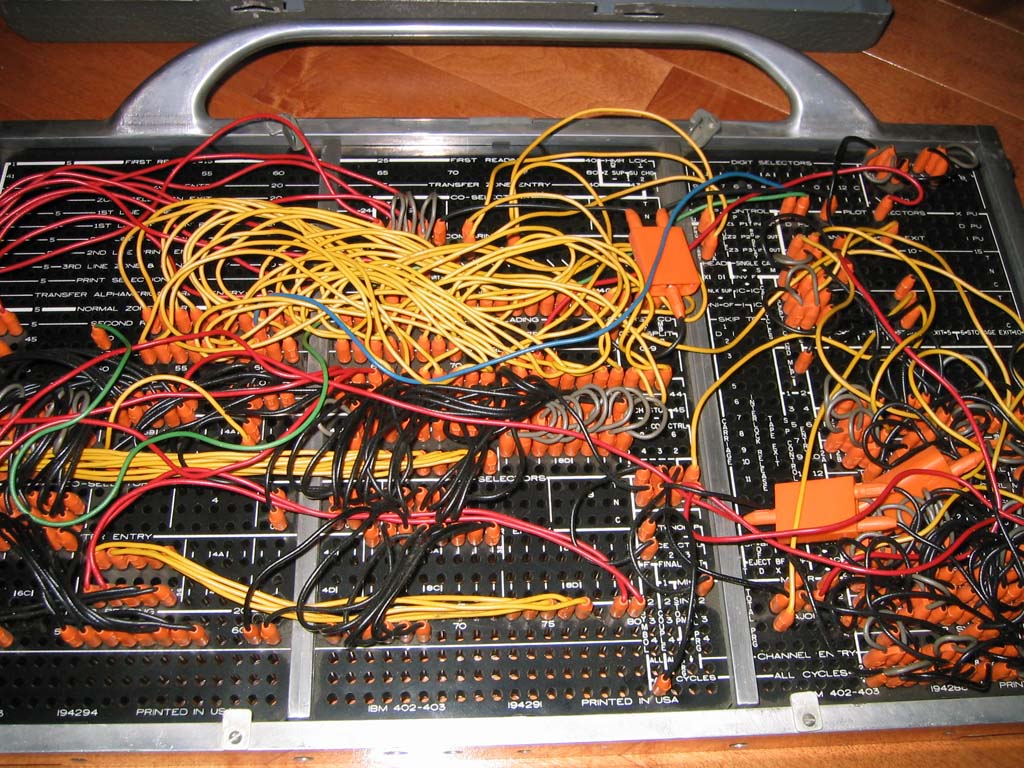
How did the plugboard work? Is it literally 31 steps across (or down, or whichever way it was oriented) and you connected the bits in each step to locations that selected an operation?
Or was it more like microcode where you had to consider some contextual implementation details as well?
The plugboard is more complex than earlier tabulators, where you would connect a wire from, say column 5 of the card input to column 12 of the print line. Or connect a card column to a counter input. Most of the wiring for the older tabulators was pretty straightforward for customers, specifying how the characters moved when a card was read.
The Univac 1004 made things more complicated in two ways. First, you had multiple steps; tabulators did one step per card (more or less). Second, the Univac 1004 had core memory, so characters were moving in and out of user-controlled storage locations, instead of directly from the card to the printer.
There are 31 holes for the "step output" (rows L through P on the panel). These get energized on steps 1 through 31 of the program. The basic idea is that you wire from a step output to everything that should happen during that step. You connect a wire from a step to the action you want to perform on that step. You also connect wires to select the two operands for the operation during this step.
The core memory is arranged as a 31 by 31 matrix. (I think it's a coincidence that 31 matches the number of steps.) To write a value to the core memory, you give the memory the two coordinates by connecting two wires (rows j through m on the panel).
For a branch, you wire to a Step Sequence Change input (row W), specifying which step should be executed next.
There are a bunch of "selectors" which are like relays that select one of two inputs. These let you implement conditional actions based on a signal (without doing a branch).
There are a bunch of "address combine" connections, which I think operate like AND gates, producing an output if there are multiple inputs.
Because everything is wired electrically, you can't simply wire two outputs to the same input or they will get shorted together. So you have "distributors", which essentially produce multiple copies of the same signal. (Internally, it's just a diode.)
The plugboard also has a lot of features that are useful for card-processing applications but may seem random, like suppressing leading zeros on a number.
It's really a different model of programming from what you're used to. I haven't looked thoroughly at how the Univac 1004 gets wired up, so my explanation is a bit hand-waving. You can look at the manual if you want to learn more.
Always thanks to Ken for all the fun "memory" lane stuff.
That board reminded me of an old PDP1 board from way back when I was doing undergrad in the 1970's and we had a "junker" PDP1 that no longer ran (replaced with new PDP8) but people would salvage things off it. It had that same old timer Resistor, Diode, Transistor type logic circuits on it.
Would love to see some of the old PDP's stuff reversed engineered if they have any of it around there. Ken if you take requests :)
"many customers found plugboard programming easier than programming with code, both because they were more familiar with it and because it is visual and direct."
If your program has only 31 steps, I'd also would prefer to program it using a plugboard panel.
The computer uses excess-three encoding for digits, adding 3 to the value before converting to binary. For example, 6 is represented as binary 1001. The advantage of this encoding is that flipping the bits yields the 9's-complement decimal value, simplifying subtraction. For example, flipping the bits of 6 yields binary 0110, which is 3 in excess-3 notation. Excess-3 representation also handles carries correctly; if you add two numbers that sum to 10, the excess-3 values will sum to 16, causing a binary carry. To convert the sum to excess-3, The value 3 must be added (if a carry) or subtracted (if no carry).
To see how addition works with excess-3, 2 + 4 in excess-3 is binary 0101 + 0111 = 1100. Subtracting 3 yields 1001, which is 6 in excess-3. But 2 + 9 is binary 0101 + 1100 = 10001, generating a carry out of the 4 bit value. Adding 3 yields 0100, which is 1 in excess-3. Considering the carry-out, this is the desired result of 11.